You have no items in your shopping cart
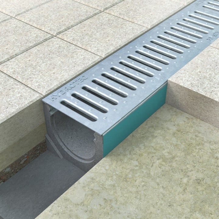
The MINI drainage channel according to DIN EN 1433 is a simple modular system for easy self-installation. The drainage channel does not require a concrete coating (type I) and can be directly asphalted or paved. With the various covering options, the channel is the ideal drainage solution for driveways in the house and on the yard.
 |
 |
 |
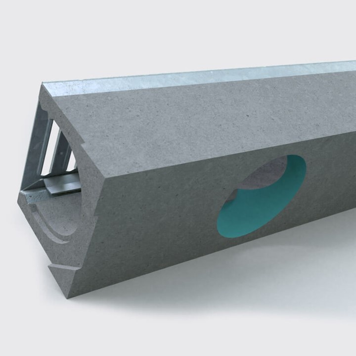 |
Ideal for tile pavingThe straight outer surfaces guarantee safe and smooth installation.
|
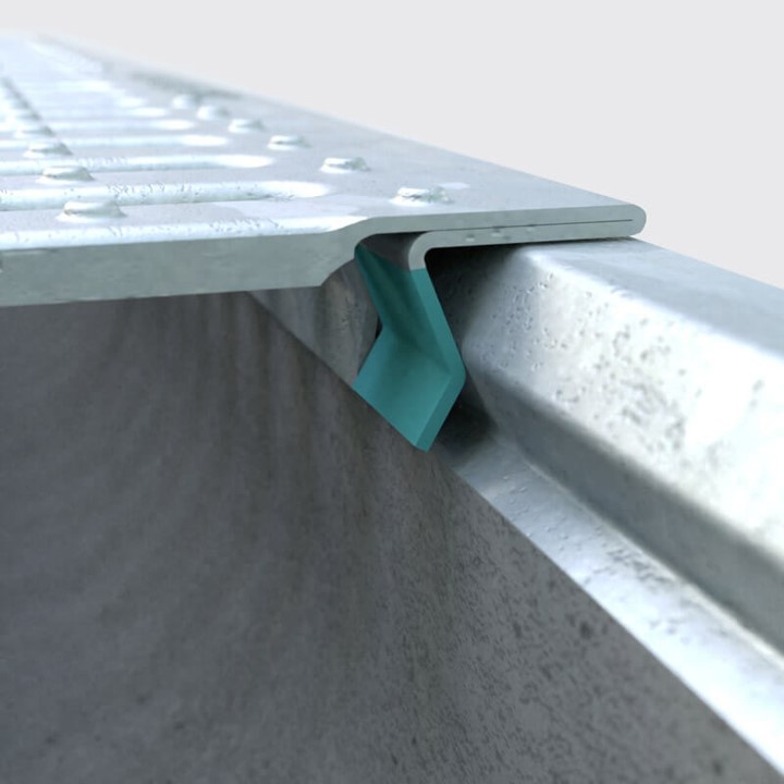
Click lockThe covers can be locked with a simple click mechanism.
|
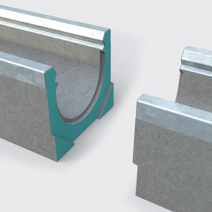
Precisely fitting cross sectionThe elements can be easily and safely pushed together using useful profiles on the front sides.
|
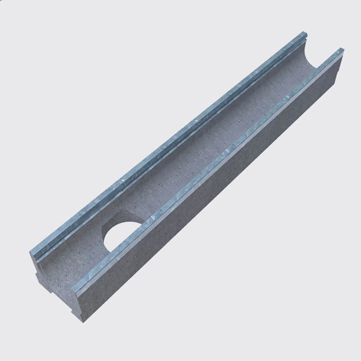
Drain elementOptionally with factory-provided hole Ø110 for PP pipe DN 100 to connect to the pipe.
|
More benefits
|
|
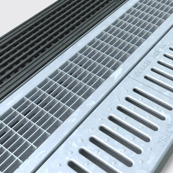
CoversGalvanized slot grille (A 15) |
Installation areas
 |
 |
 |
Home |
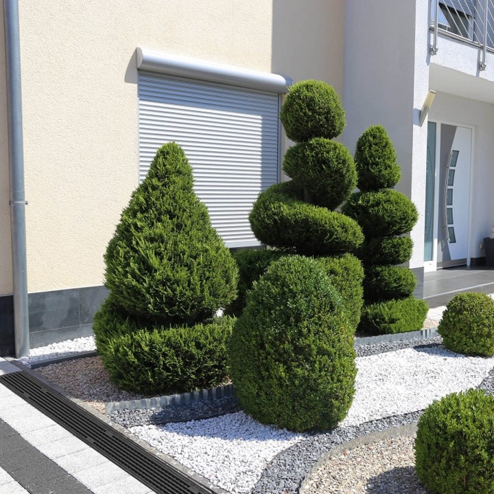
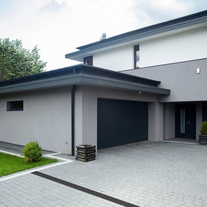
Entrances to the house and courtyard |
Pedestrian area |
Installation instructions
Step by step installation instructions
The MINI drainage channel is a simple modular system and can be installed without complicated procedures. Ideal for the DIY enthusiast or do-it-yourselfer.
 |
 |
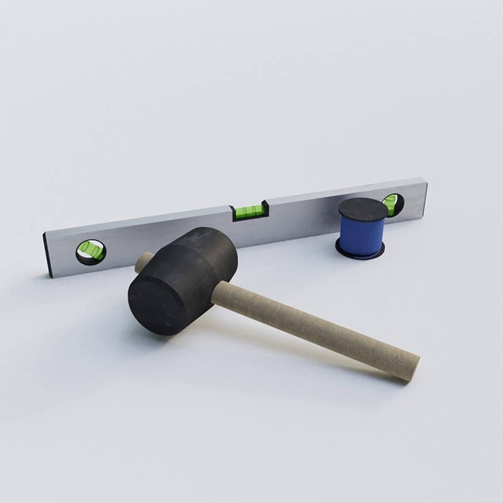
1) PreparationBefore installation, plan how rainwater will be drained, e.g. via an existing underground pipe or a nearby ditch. Recommended tools for installation: rubber mallet, spirit level and straightedge with retaining rods.
|
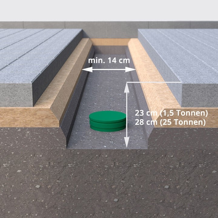
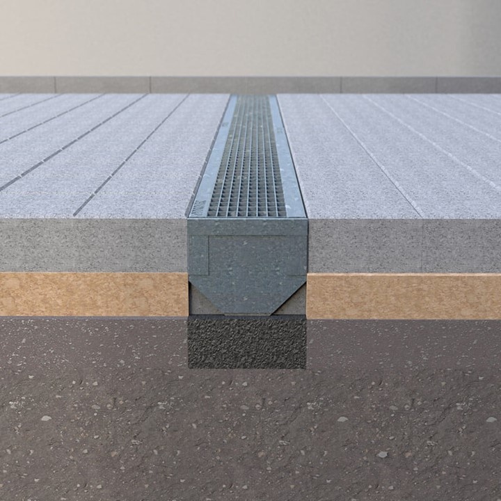
2) Dig a trenchThen remove the paving stones and dig a trench with a total depth of 23 cm (for a load of 1.5 tons) or 28 cm (for a load up to 25 tons). The width of the trench must be at least 14 cm.
|
 |
 |
 |
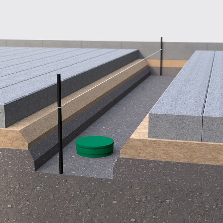
3) Determine positionThe course of the drainage channel is determined with a guide line. The ruler is also used later to level the gutter elements. The height of the string must be 5 mm lower than the top edge of the paving.
|
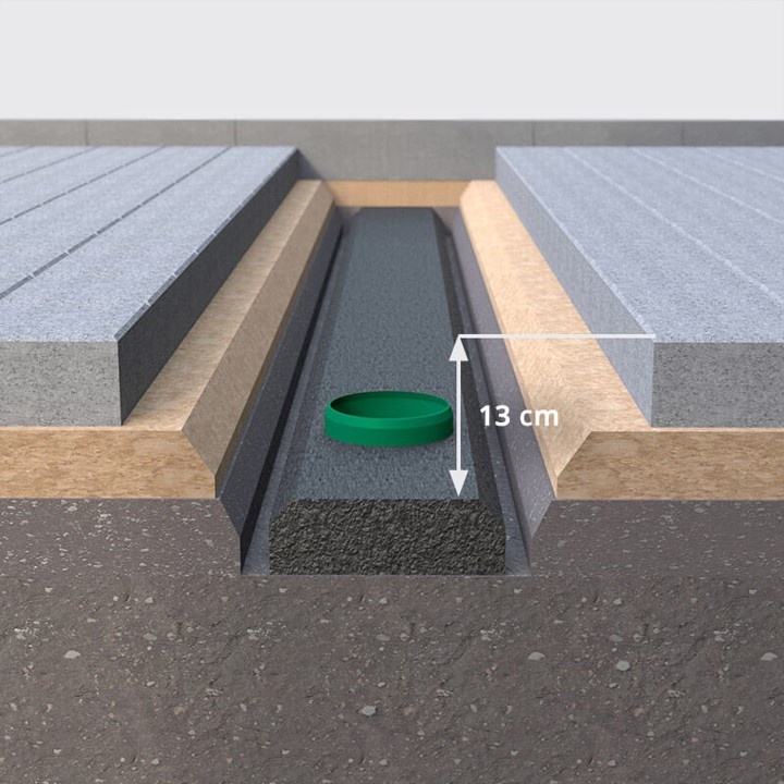
4) Pour concrete foundationThe pipe of the base line is extended with a pipe sleeve. A concrete foundation with a quality of C25/30 is placed in the trench. The distance from the foundation to the upper edge of the paving must be 13 cm. The gutter elements are placed when the concrete is moist. |
5) Determine the start of the installationThe installation of the drainage channel begins with the channel element that serves to drain the water. A drainage element with a hole for KG pipes DN 100/110 is recommended for this. Alternatively, inlet boxes can also be used. The concrete bed must be moist before installation. |
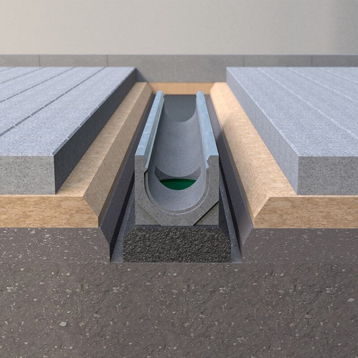 |
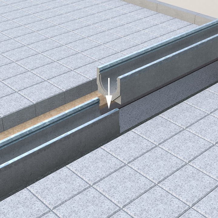 |
6) Set the drain elementThe drain element is placed on the pipe or on the concrete bed. The pipe opening is closed until installation is complete, so that no dirt can enter the pipe.
|
7) Lay more gutter elementsWhen laying, care should generally be taken to ensure that the individual gutter elements are fitted vertically and not pushed into each other! The cover grilles are then fitted and locked into place. Use a rubber mallet to level the gutters on the guide line.
|
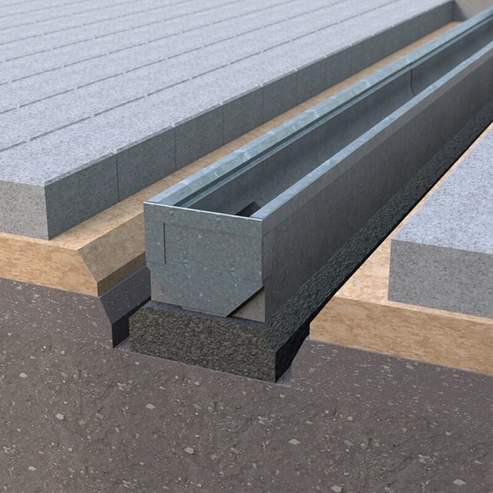 |
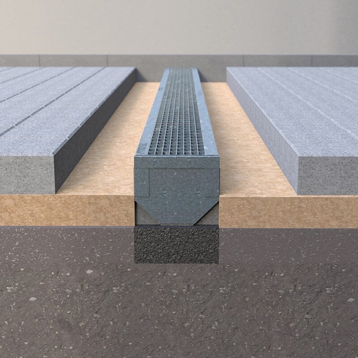 |
 |
8) Install end platesPlace the matching end walls at the respective ends of the gutter line.
|
9) Ground cover and pavingPlace the foundation layer and paving bed around the drain.
|
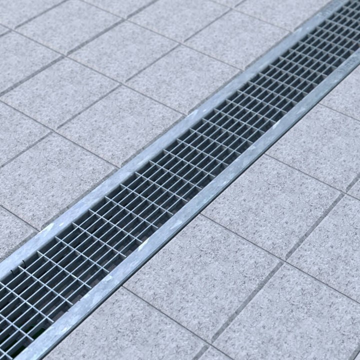
10) PavingThe paving stones are against the drainage channels. The upper edge of the drainage channel must be permanently approx. 5 mm lower than the adjacent paving. The existing sand is swept into the joints of the paving stones. |
 |
 |
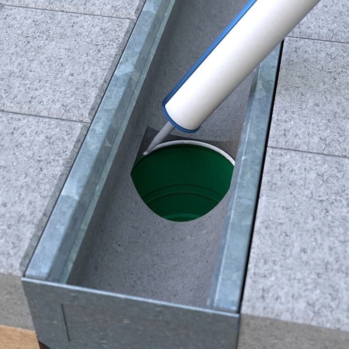
11) Drain element sealFinally, the drain pipe is sealed with a sealant.
|
12) Sealing gutter elementsSeal the joints between the gutter elements with a sealant. The drain gutter is then ready for use. |
DWTN accepts no liability for incorrect installation of the drainage channel.
Installation direction
| The installation direction of the gutters is always against the flow direction and starts at the connection to the base pipe or at the sand trap element. If the elements are laid in two different directions, the profile groove must be removed with a flex or end walls must be used at the meeting of the elements to prevent a gap. When laying, it must generally be ensured that the individual gutter elements are installed vertically and not pushed against each other! | 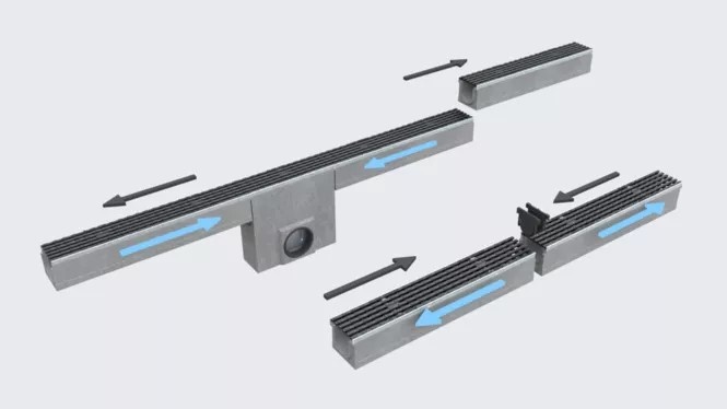 |
Principles of Drainage Channel Construction
- All delivered parts must be checked for perfect condition. Damaged parts must not be installed!
- The choice of the most suitable installation method for your case is the responsibility of the commissioned specialist consultancy firm, which has the necessary knowledge to assess the situation.
- The type of installation of the drainage channels depends on the installation locations with the associated traffic load and the planned hardening. The installation locations are divided into classes A 15 to F 900 in EN 1433. From class C, all cover grilles must be secured in a traffic-safe manner. The foundation of the drainage channels must be in accordance with the traffic load.
- Horizontal loads from traffic or the thermal behaviour of the pavement must be absorbed by a sufficiently dimensioned concrete lining of the gutter bodies and by expansion joints that are applied in the longitudinal direction of the gutter, in particular in adjacent concrete surfaces. Joints transverse to the gutter series must always be applied to the gutter joint. The installation direction of the gutters always runs against the flow direction and starts at the connection to the sewer.
- Adjacent paving must be placed 5 mm higher than the surface of the cover grid or edge protection, taking into account subsequent settlement and subsidence. Appropriate measures must be taken to prevent the road surface and gutters from washing away and flooding.
- Where extreme horizontal forces are expected across the drainage channel, e.g. at road crossings, slip roads or on motorways, the drainage channels must be secured laterally with reinforced road surface concrete.
Load classes according to DIN EN 1433
 |
 |
 |
 |
 |
 |
| Class A 15 | Class B 125 | Class C 250 | Class D 400 | Class E 600 | Class F 900 |
| Footpaths, cycle paths, green areas | Pedestrian zones, parking lots | Roadsides, parking spaces | Public roads and parking lots | Industry, defense, high wheel loads | Airports, industrial estates, very high wheel loads |

