You have no items in your shopping cart


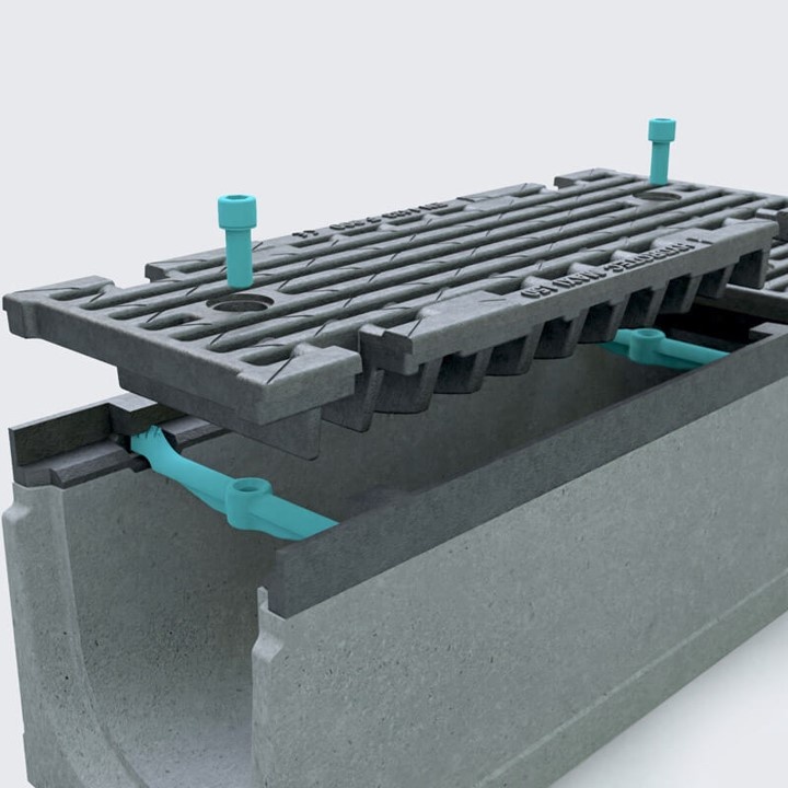
The drainage channel for the highest demands on traffic safety with two special screw locks per cover grid. Ideal for industrial estates, airports, race tracks and ports. The channel can withstand maximum forces and loads up to class F 900 and offers resistance and sufficient fire resistance due to the concrete quality C35/45.
 |
 |
 |
 |
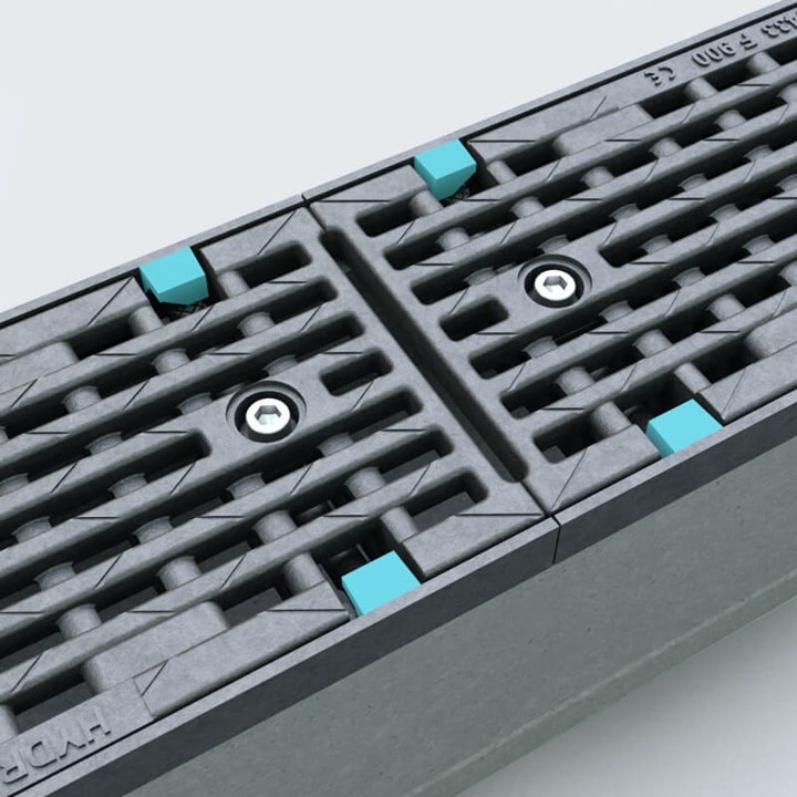
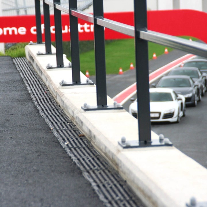
Special screw locksTwo special screw locks per cover grille guarantee traffic safety in all load classes and thus allow the MAXI F1 system to meet even the highest safety requirements.
|
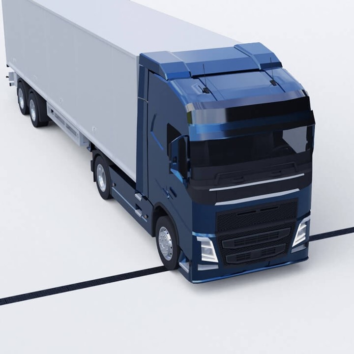
High load capacityThe absorption of maximum suction and braking forces and sufficient fire resistance are requirements for built-in components in extremely busy traffic areas.
|
Protection against length shiftThanks to 8 anti-shift points per linear metre, the braking forces in the longitudinal direction are excellently absorbed and (supported) further transmitted.
|
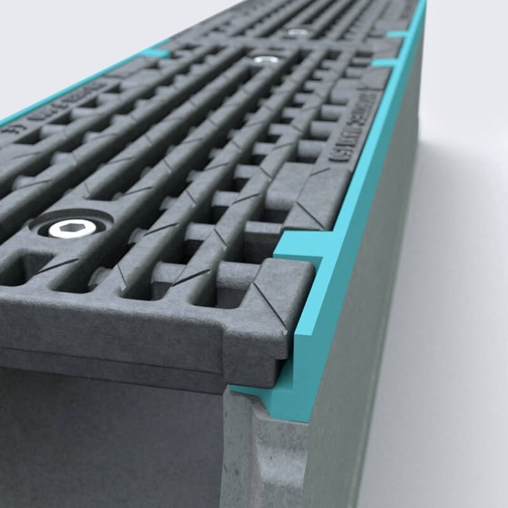
Edge protectionMaximum stability in all classes due to the 5 mm thick edge protection made of nodular cast iron.
|
More benefits
 |
 |
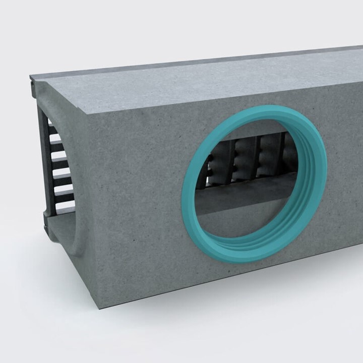
Drain elementLiquid-tight connection (incl. sealing ring) for a plastic pipe. |
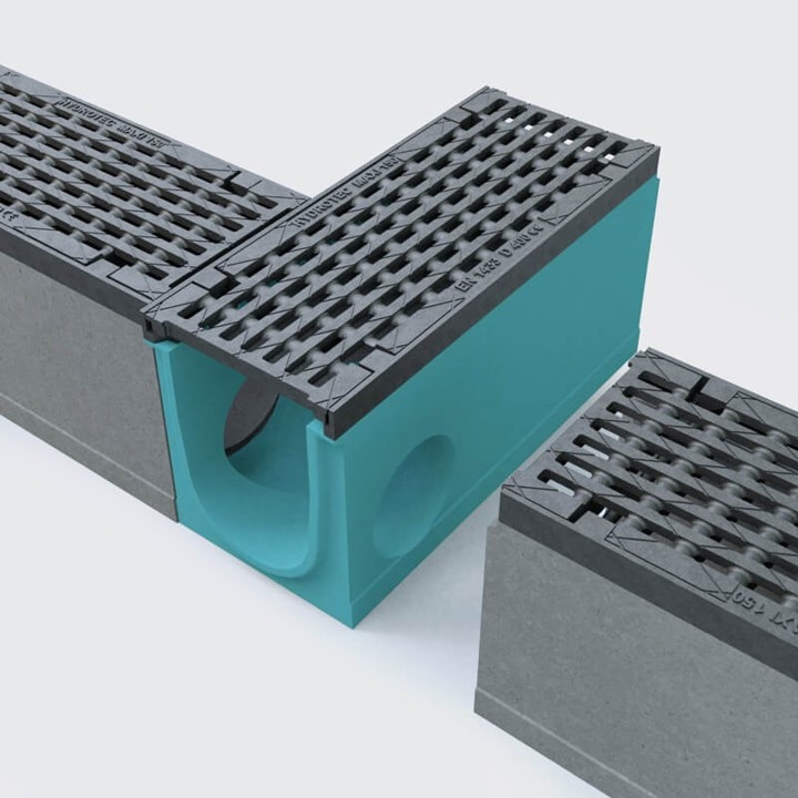
Special elementCan be used as a corner or T-piece. |
References
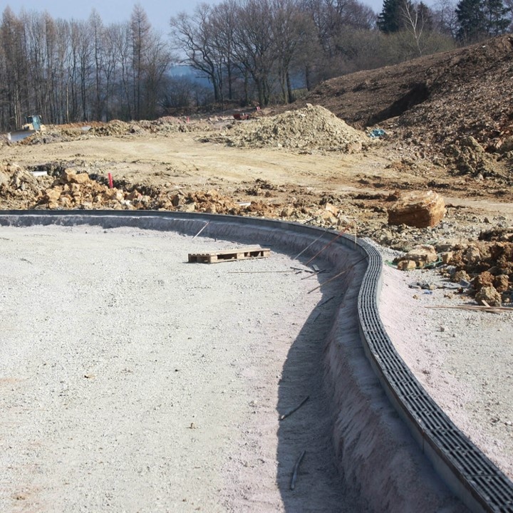
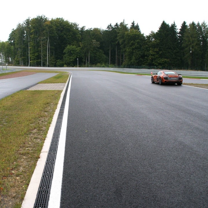
Drainage channels on Bilster Berg
Our MAXI F1 drainage channel was installed in 2013 at the Bilster Berg Drive Resort in the Teutoburg Forest. The Drive Resort near Bad Driburg currently covers 82 hectares and was built on a former military site. In addition to the research and development opportunities for the automotive industry that the approximately 4.2 km long circuit offers, brand cups, driving and safety training and other events are held here.
The projectThe track, located on the Bilster Berg, is adapted to the natural conditions, so that when driving, approximately 70 metres of altitude difference with gradients of up to 10% must be overcome. The project was financed exclusively from private funds; the total investment volume for the planning and construction of the track amounted to approximately 34 million euros. The idea came from local entrepreneur Marcus Graf von Oeynhausen-Sierstorpff, who was supported by, among others, F1 circuit architect Hermann Tilke and rally expert Walter Röhrl. HYDROTEC Technologies AG was commissioned to supply the drainage technology with manhole covers and drainage channels, which ensure targeted drainage of the track and thus safe driving. |
|
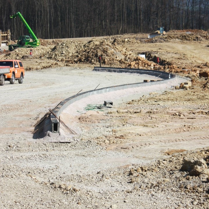 |
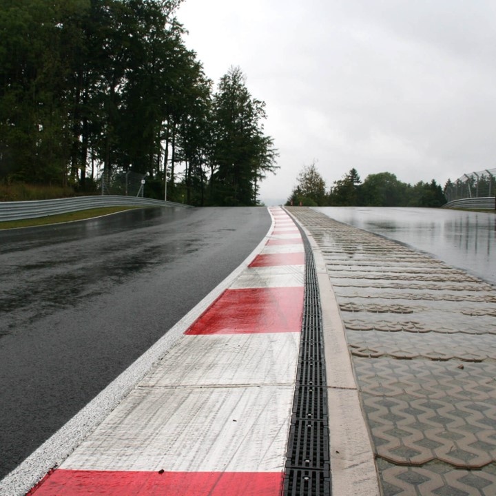
Drainage channel MAXI F1The MAXI F1 drainage channel was used for the test track. This drainage channel was specially developed for the requirements of a race track and has already been installed on the new Formula 1 circuit in Istanbul. The MAXI F1 locking system in particular meets the extremely high requirements for high safety. A total of 4,385 meters were installed. |
 |
 |
 |
Installation direction
| The installation direction of the gutters is always against the flow direction and starts at the connection to the base pipe or at the sand trap element. If the elements are laid in two different directions, the profile groove must be removed with a flex or end walls must be used at the meeting of the elements to prevent a gap. When laying, it must generally be ensured that the individual gutter elements are installed vertically and not pushed against each other! | 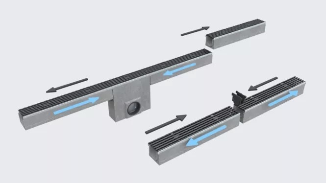 |
| Flow direction = blue arrows, laying direction = black arrows |
Principles of Drainage Channel Construction
- All delivered parts must be checked for perfect condition. Damaged parts must not be installed!
- The choice of the most suitable installation method for your case is the responsibility of the commissioned specialist consultancy firm, which has the necessary knowledge to assess the situation.
- The type of installation of the drainage channels depends on the installation locations with the associated traffic load and the planned hardening. The installation locations are divided into classes A 15 to F 900 in EN 1433. From class C, all cover grilles must be secured in a traffic-safe manner. The foundation of the drainage channels must be in accordance with the traffic load.
- Horizontal loads from traffic or the thermal behaviour of the pavement must be absorbed by a sufficiently dimensioned concrete lining of the gutter bodies and by expansion joints that are applied in the longitudinal direction of the gutter, in particular in adjacent concrete surfaces. Joints transverse to the gutter series must always be applied to the gutter joint. The installation direction of the gutters always runs against the flow direction and starts at the connection to the sewer.
- Adjacent paving must be placed 5 mm higher than the surface of the cover grid or edge protection, taking into account subsequent settlement and subsidence. Appropriate measures must be taken to prevent the road surface and gutters from washing away and flooding.
- Where extreme horizontal forces are expected across the drainage channel, e.g. at road crossings, slip roads or on motorways, the drainage channels must be secured laterally with reinforced road surface concrete.
Load classes according to DIN EN 1433
 |
 |
 |
 |
 |
 |
| Class A 15 | Class B 125 | Class C 250 | Class D 400 | Class E 600 | Class F 900 |
| Footpaths, cycle paths, green areas | Pedestrian zones, parking lots | Roadsides, parking spaces | Public roads and parking lots | Industry, defense, high wheel loads | Airports, industrial estates, very high wheel loads |