You have no items in your shopping cart


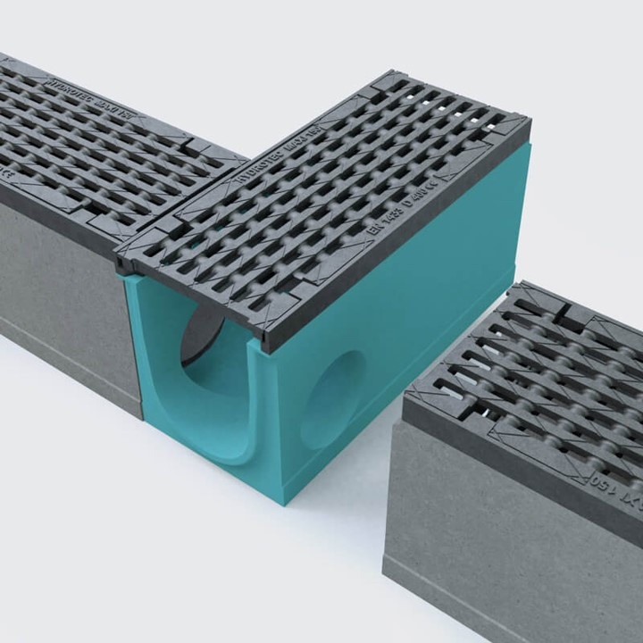
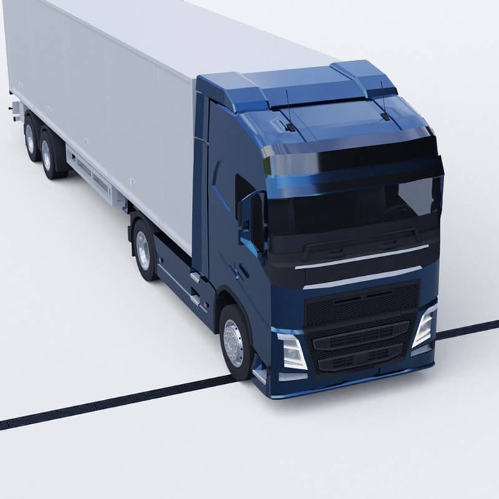
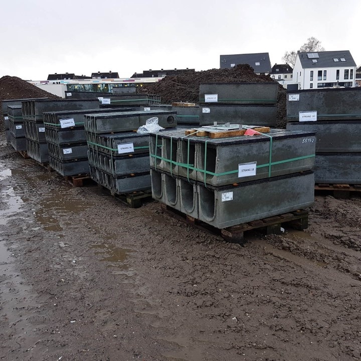
The MAXI drainage channel is the all-rounder among concrete drainage channels and can be used in a variety of ways, from drainage with lower requirements to higher requirements in heavily loaded areas. Due to the screwless locking, protection against lengthwise displacement and the strong edge protection, the MAXI system is ideally suited for industrial areas with freight traffic, airports, truck parking areas, but also for the drainage of roadways, cycle paths and pavements.
 |
 |
 |
 |
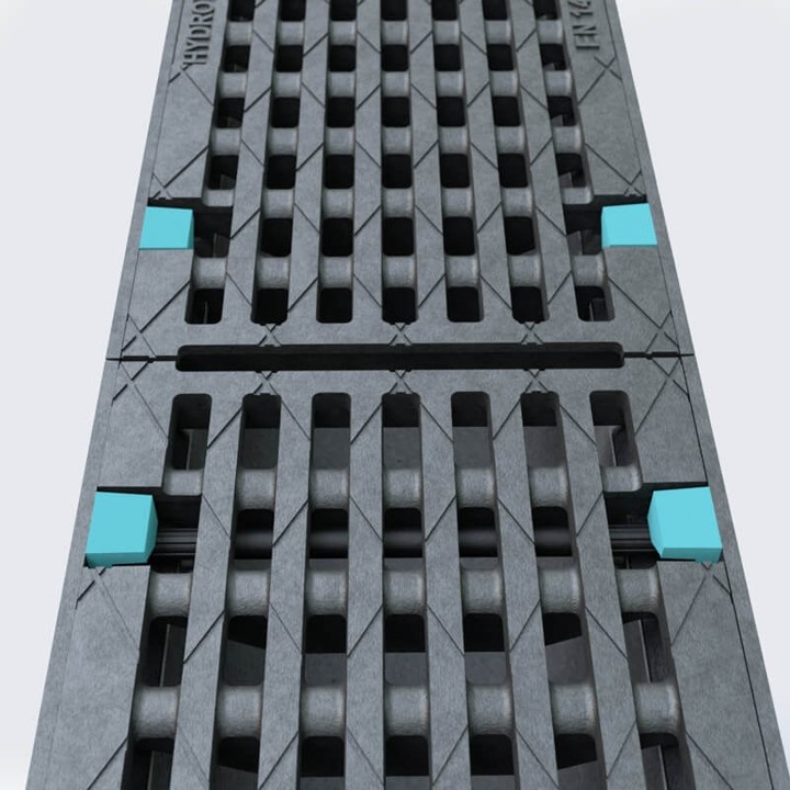
Protection against length shiftThanks to 8 anti-slip points per linear metre, the braking forces in the longitudinal direction are excellently absorbed and transferred.
|
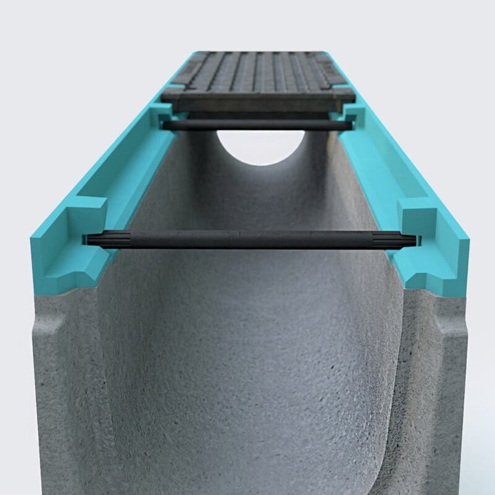
Edge protectionMaximum stability in all classes due to the 5 mm thick edge protection made of nodular cast iron.
|
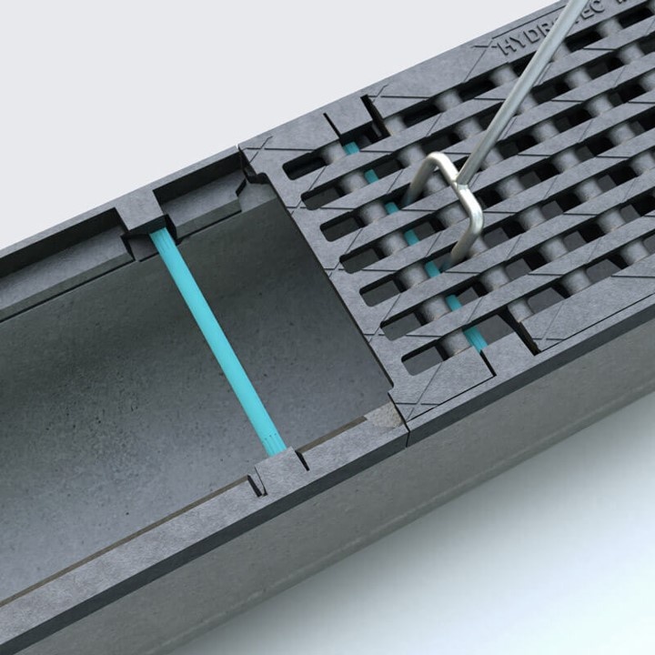
Screwless lockThe covers are equipped with a simple locking system, which can be locked and unlocked using the mounting rod (accessory). |
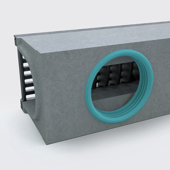
Drain elementLiquid-tight connection (incl. sealing ring) for a plastic pipe.
|
More benefits
 |
 |
Special elementCan be used as a corner or T-piece. |
High load capacityThe MAXI is suitable for loads up to class F 900. |
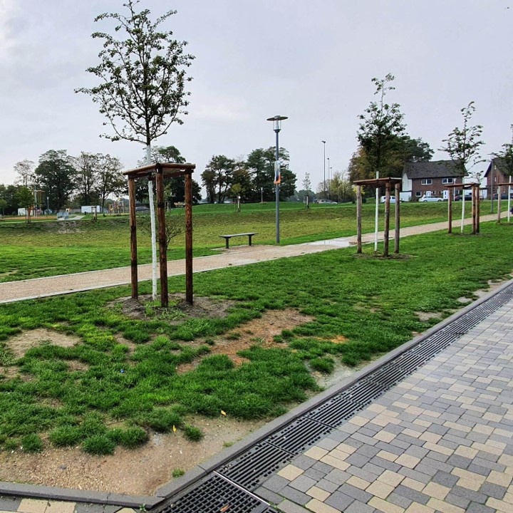
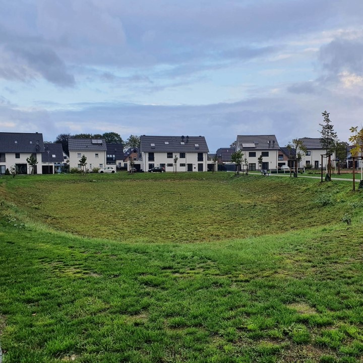
Well-considered water management
Here you can see what a future-oriented urban and village development can look like, taking into account a water-sensitive street design with drainage close to the surface.
Sealed surfacesThe increase in paved surfaces in recent years has had significant consequences for the water management of cities and municipalities. Consequences such as the reduction of groundwater recharge, a changed local climate due to a lack of evaporation as a result of surface water runoff and the risk of flood peaks pose new challenges for transport planners. These after-effects of the existing sealing are exacerbated by the continuous expansion of road traffic, a growing demand for settlement areas and the predicted, if not already existing, climate change. Here you can see what a future-oriented urban and village development can look like, taking into account a water-sensitive road design with drainage close to the surface. |
 |
 |
Laying the foundations, planning carefullyEven before the zoning plan comes into force, you can commission an expert investigation into the seepage capacity of the subsoil. This should provide information about the building site, the possible type of infiltration and the construction of the infiltration facilities. Several ram core drillings, each to a depth of 4.0 m, provide information about the permeability coefficient of the subsoil. In addition, it can be determined whether groundwater is present up to the final depth of a maximum of 4.0 m below ground level. The results of the investigations may show that the conditions in the subsoil allow infiltration of precipitation water via pipe trenches or drainage channels in accordance with DWA worksheet A 138 ("Planning, construction and operation of facilities for infiltration of precipitation water") into the permeable, clay-free sands. Nothing therefore stands in the way of the planning and implementation of decentralised infiltration of precipitation water on the plots in accordance with § 51a of the NRW Water Act (from 2009). |
 |
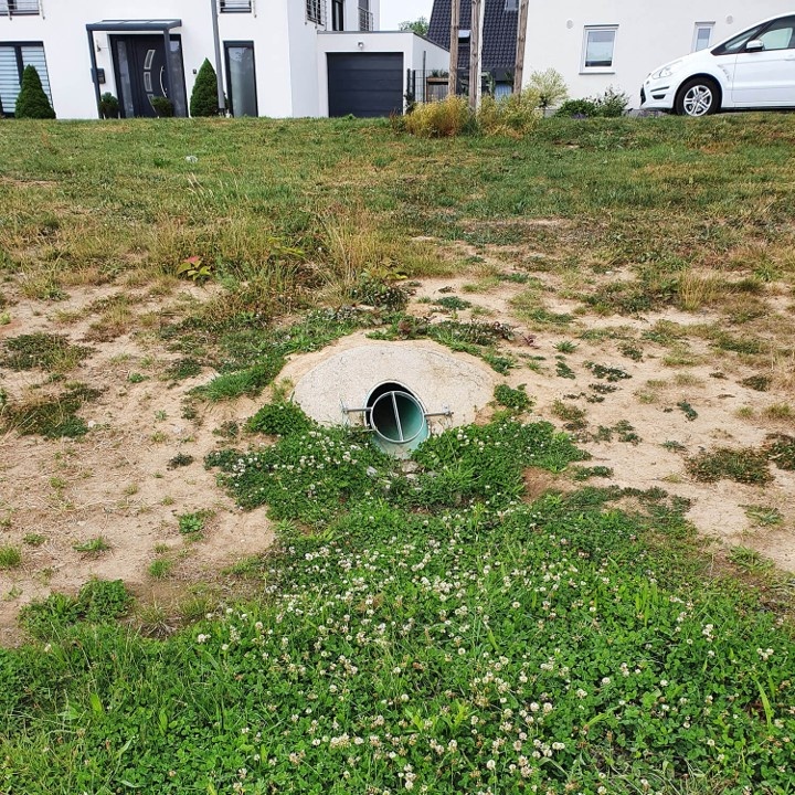 |
| The infiltration of surface water into water basins is both ecologically and economically preferable to direct discharge into the sewer system. |
Discharge of surface water via pipe systems to the swamp.
|
Showing the water in the right wayRainwater management in urban areas places high demands on the planning of municipalities. At the same time, however, there are extensive possibilities for the design of cities and open spaces and the reduction of the risk of flooding in buildings and infrastructure (flood prevention). While in previous decades attempts were made to drain rainwater as quickly as possible to the sewer or a receiving watercourse, today the highest priority is given to infiltration on the property or in public spaces and to the creation of retention areas. In order to prevent surface water from finding its own way, structures are needed that guarantee targeted, rapid drainage. |
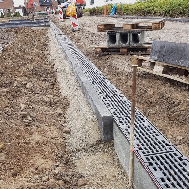 |
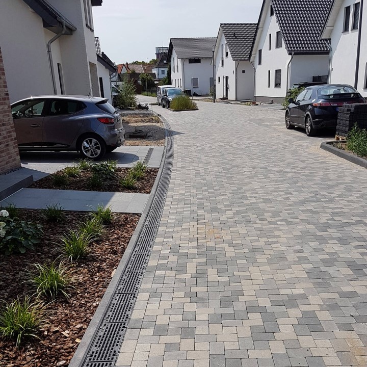
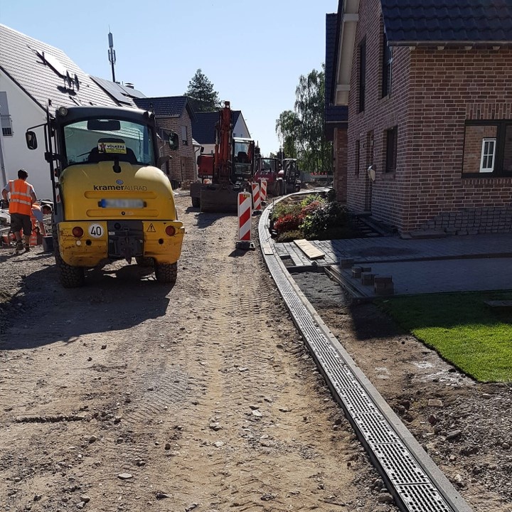
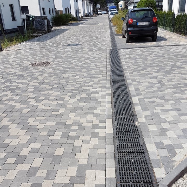
Safe and fast disposalIn the context of the planning of the drainage of the traffic areas in the construction area, a verge drainage was planned that had already proven itself. The MAXI linear drainage system was used. Depending on the hydraulic performance requirements, channel elements with four different nominal widths (100 to 300) were installed. You can rely on drainage channels with screwed cover grilles or with screwless locking. |
Eight shear safety points per linear metre absorb and transfer braking forces in the longitudinal direction, for example. Anchoring ribs to prevent "floating" and preforms for vertical DN 100/150 drains complete the advantageous properties of the MAXI drainage system. In this project, the installed roadside drainage system also takes over the task of the roadside ditches, which absorbs surface water in conventional applications. Via the gutter elements with a nominal width of 300 mm, the water reaches the short sewer line via a channel, which ends in the wadi. |
 |
 |
 |
 |
References
 |
 |
 |
 |
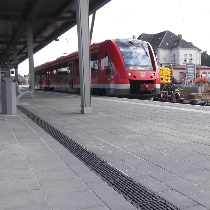
Train stations |
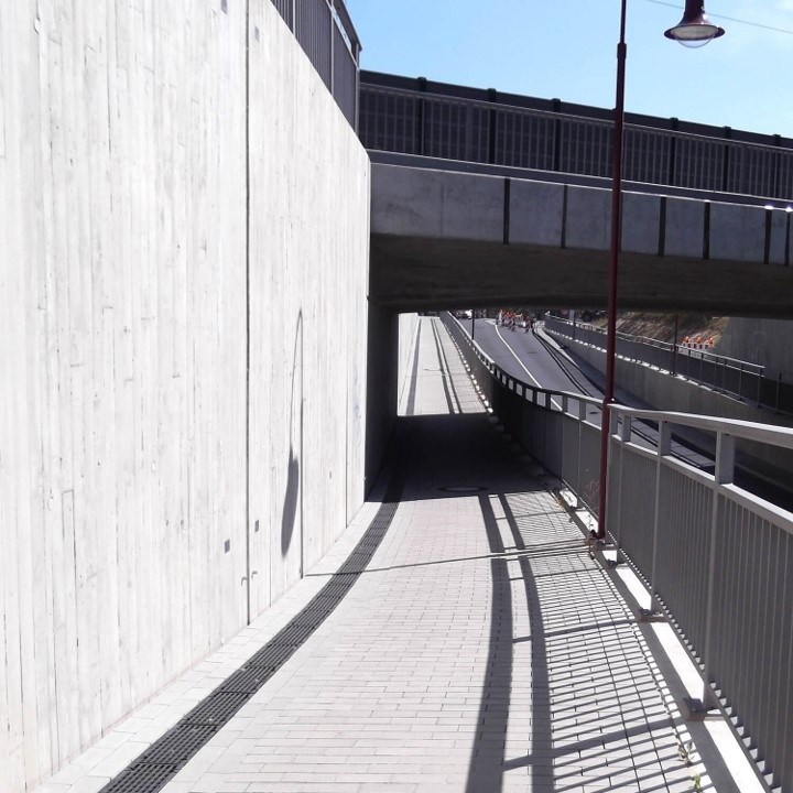
Tunnels |
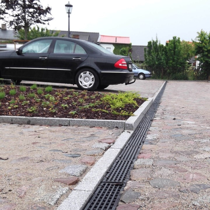
Parking lots |
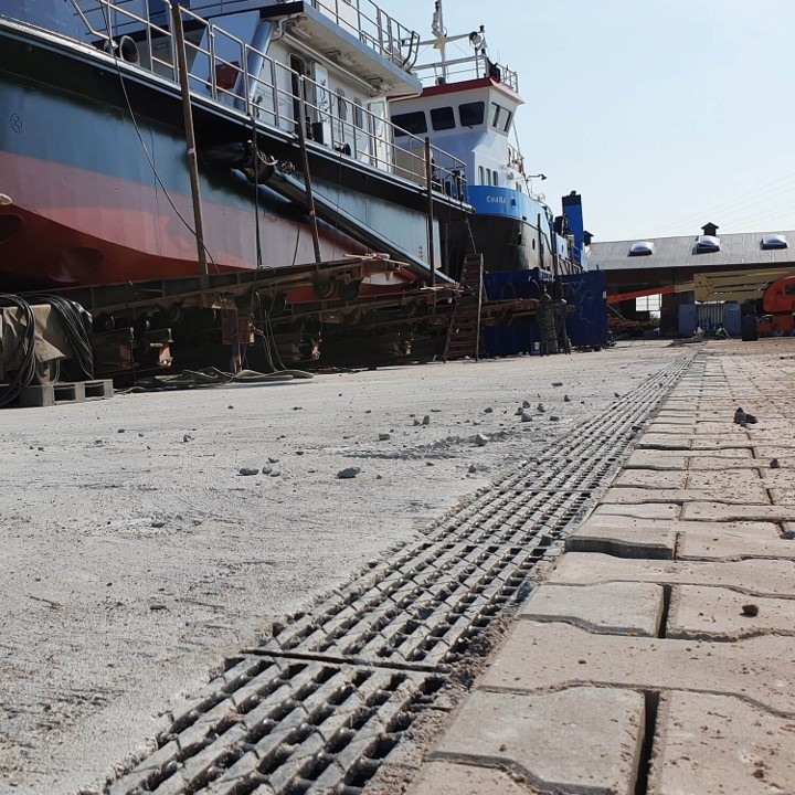
Shipyards |
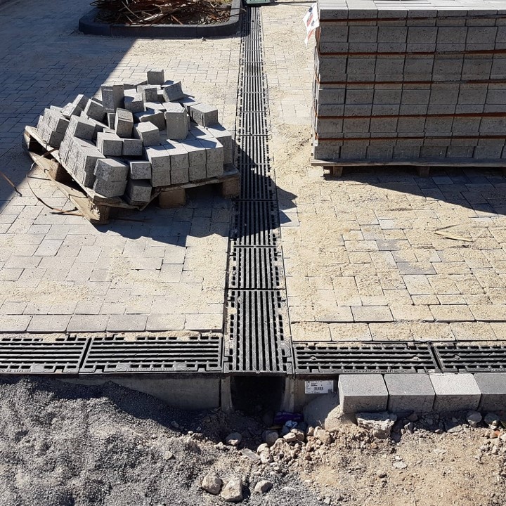
Installation direction
| The installation direction of the gutters is always against the flow direction and starts at the connection to the base pipe or at the sand trap element. If the elements are laid in two different directions, the profile groove must be removed with a flex or end walls must be used at the meeting of the elements to prevent a gap. When laying, it must generally be ensured that the individual gutter elements are installed vertically and not pushed against each other! | 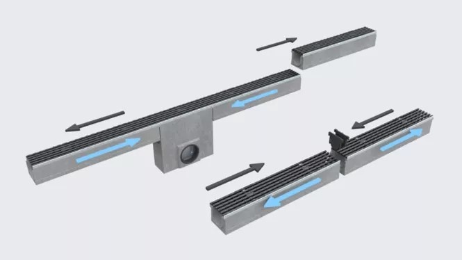 |
| Flow direction = blue arrows, laying direction = black arrows |
Principles of Drainage Channel Construction
- All delivered parts must be checked for perfect condition. Damaged parts must not be installed!
- The choice of the most suitable installation method for your case is the responsibility of the commissioned specialist consultancy firm, which has the necessary knowledge to assess the situation.
- The type of installation of the drainage channels depends on the installation locations with the associated traffic load and the planned hardening. The installation locations are divided into classes A 15 to F 900 in EN 1433. From class C, all cover grilles must be secured in a traffic-safe manner. The foundation of the drainage channels must be in accordance with the traffic load.
- Horizontal loads from traffic or the thermal behaviour of the pavement must be absorbed by a sufficiently dimensioned concrete lining of the gutter bodies and by expansion joints that are applied in the longitudinal direction of the gutter, in particular in adjacent concrete surfaces. Joints transverse to the gutter series must always be applied to the gutter joint. The installation direction of the gutters always runs against the flow direction and starts at the connection to the sewer.
- Adjacent paving must be placed 5 mm higher than the surface of the cover grid or edge protection, taking into account subsequent settlement and subsidence. Appropriate measures must be taken to prevent the road surface and gutters from washing away and flooding.
- Where extreme horizontal forces are expected across the drainage channel, e.g. at road crossings, slip roads or on motorways, the drainage channels must be secured laterally with reinforced road surface concrete.
Load classes according to DIN EN 1433
 |
 |
 |
 |
 |
 |
| Class A 15 | Class B 125 | Class C 250 | Class D 400 | Class E 600 | Class F 900 |
| Footpaths, cycle paths, green areas | Pedestrian zones, parking lots | Roadsides, parking spaces | Public roads and parking lots | Industry, defense, high wheel loads | Airports, industrial estates, very high wheel loads |